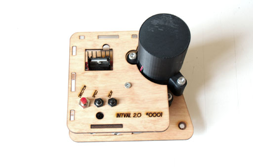
INTVAL 2.0
Intervalometer for Bolex 16mm Cameras
Project Home - git.sixteenmillimeter.com/16mm/intval2
Github Mirror - github.com/sixteenmillimeter/intval2
1) Overview
The INTVAL 2.0 is an open-source open-hardware intervalometer for Bolex 16mm cameras. It enables you to expose single frames of film at a regulated interval. Utilizing the 1:1 shaft in Bolex cameras (Rex 4 and later models) the INTVAL 2.0 can complete a full rotation of the shutter in either 1 or 2 seconds. This allows for a range of long exposure options when used in concert with the Rexofader.
2) Attachment
To attach the INTVAL 2.0 to a Bolex camera, disable the motor and line up the four standoffs with the mounting holes on the body of the camera and insert the key into the 1:1 shaft. This can be done by laying the camera on its side--with the mounting holes facing up--and placing the INTVAL 2.0 on top of the body and making sure the key fits into the slotted 1:1 opening. If you have never attached anything to the mounts before, you may have to remove small screws that are in the holes. This opens up the mounting holes for the screws that will hold the intervalometer in place. There are four standoffs and screws, but only three need to be attached to maintain the hold required for operation.
3) Usage
The INTVAL 2.0 has two physical interfaces: the buttons on the case and the shutter
release cable. The shutter release cable plugs into the underside of the case, next
to the DC adapter, and triggers the camera. A single, short press will trigger a single
frame. Holding down the shutter release for more than 1 second will start a continuous sequence
of frames. Hitting the shutter release during a running sequence will stop the intervalometer.
The buttons on the case control three variables: direction, speed and delay. The direction of the
camera can be set to forwards (default) with a quick press, and set to backwards by holding the
button for more than 1 second.
Similarly, the speed can be set to 1 second rotation (default) with a
quick press and set to 2 second rotation by holding the button for more than 1 second. Remember,
during the 1 or 2 seconds that the shutter is rotating, exposure only occurs for a fraction of that time. How large a fraction depends on the setting of the Rexofader.
Delay refers to the time the intervalometer pauses between frames and only matters when running a sequence. The delay is set to 42 ms by default and will be set to however long you hold it down for; holding the button for10 seconds will set the delay between each frame to 10 seconds. Pressing the button quickly will reset the timer to the default 42 ms.
4) Power
Power the INTVAL 2.0 with 12VDC to the 2.1mm DC power jack located on the bottom of the case. The maximum draw of the motor is under 1 Amp, so that much current should be ample to run the intervalometer. Portable batteries, such as those used as supplimental cellphone power supplies, can be used to as mobile power sources, but they must be able to provide 12V and not the typical 5V that many of these batteries provide.
Two examples:
Rechargeable 3800mAh Lithium Ion Battery Pack with DC Connector, 12 volt
12V wall warts that can provide 1 Amp or over are also viable options for shooting in a controlled environment.
5) Creating Your Own
All parts of the INTVAL 2.0 are reproducible via 3D printing, laser cutting or are purchasable (example links are to Amazon or Adafruit) for a total build cost of ~$50. The files in this repository consist of .SCAD, .STL, .DXF and .INO files. The .SCAD files contain all the elements needed to generate the physical body of the intervalometer with .DXF files for laser cutting and .STL files for 3D printing. The .INO file contains the source code for the Arduino sketch that powers the INTVAL 2.0.
A. 3D Printing
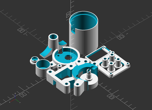
The most time-consuming part of this build should be 3D printing the parts for the INTVAL 2.0. Depending on the size of your printing bed it is most likely possible to print all parts in one convenient plate. As will be addressed later, the laser-cuttable elements can also be 3D printed if you lack access to a laser cutter.
In the /dist directory of the repo, you will find all of the .STL files needed to build the intervalometer. If needed, the .SCAD file can be used to generate additional .STL models, or it can be modified to produce unique parts to your own specifications.
The most delicate and integral piece to be fabricated on a 3D printer is the motor_key, which interfaces the intervalometer to the 1:1 shaft of the Bolex. This part should be printed as close to solid as your printer allows or you should look at a third-party printing service to have it made from stronger materials than the typical PLA or ABS used by most home printers. That said, I have used an ABS-printed motor key extensively with no issues thus far.
B. Laser Cutting
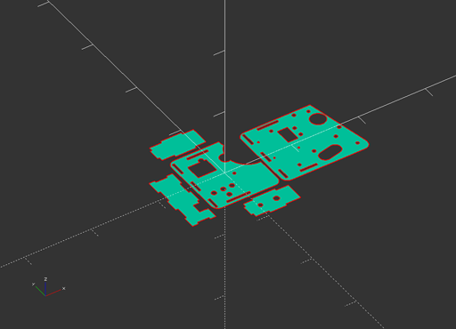
The INTVAL 2.0 has a flat panel on which all parts and electronics are mounted. For this reason, and to reduce production time, a laser cutting component has been added. See the much earlier--and now deprecated--attempt to have an entirely printable model in the original INTVAL (or INTVAL Next as I had taken to calling it on Thingiverse). Printing the flat base of this version took upwards of 3 hours on my modest printer, and with the accessibility of laser cutters at hacker/maker spaces becoming more common I decided this was feasible to include in my design.
Important to note: A laser cutter is not required to make this intervalometer. If you have access to a 3D printer, it's very possible to use the .SCAD files to generate .STLs of the parts designated for cutting. Make sure that they are all set to 3.175mm thickness as the design requires 1/8" materials for assembly. A clever person could even improve the design to remove the need for bolts to attach the motor_mount_bottom and electronics_mount pieces when making a 3D printed version.
Another note: When cutting the base of the intervalometer, named the panel_laser there is a circular cut for a skateboard wheel bearing to be inserted. These are made with slightly different tolerances, so do some tests before you cut your final panel. When properly scaled, the bearing should fit tightly so that it can be glued to the panel. The positioning of the bearing is vital to the functionality, so it's best to test the bearing fit using the bearing_calibrate module and then edit the size of the bearing by changing the fuzz variable of the bearing_laser module. Export a new .DXF of the intval_panel_laser module by using the projection() function and cut that.
Materials
Early prototypes for the INTVAL 2.0 were made with 1/8" acrylic. I was very hopeful that I would be able to make a visually clear product where all of the electronics would be visible. Cool, right? This, unfortunately, was not to be. The forces applied to the prototypes during casual use would cause the acrylic to crack or shatter quite easily. I'm not saying it's not possible, but just that it is a less-than-ideal material for this project.
Here's what I would suggest, in order (all should be cut from 1/8" sheets):
- Craft plywood - Cheap, flexible and effective. I cut this, add custom designs, stain and coat in polyurethane. Yet to have any issues with it.
- Delrin (acetal homopolymer) - Too rich for my blood, but should perform better than acrylic. Will probably look pretty cool.
- Acrylic - Good for prototyping, but may crack under pressure. Make parts to spare if you go down this path.
C. Hardware
I would like to further reduce the amount of non-fabricated parts required for this build in future revisions, but here we are. I've run a few spreadsheet models and have the cost-per-unit down to ~$50, but this fails to account for shipping, misprints and a whole host of associated costs, including build time. Needless to say, I don't see a profitable enterprise being build on the production of 16mm intervalometers, which is why I am creating this in the open for others to build and improve upon.
Links below are to Amazon for accessibility and Adafruit where possible, but feel free source compatible or equivalent materials from companies that align to your personal ethics. Sourcing from AliExpress can bring the cost-per-unit down dramatically, if you are building these as part of a workshop or class.
The meat of this project are the L298N Dual H-Bridge and the Arduino Trinket 5V. The 3D models are designed for the 60RPM motor listed below, but the design can easily be adapted to other motors. I'm trying out other motors in a few different forks of this project.
All of the purchasable parts for this build:
- (1x) Arduino Trinket Pro 5V - [Adafruit] [Amazon]
- (1x) 120RPM 12VDC Motor - [Amazon]
- (1x) L298N Breakout Board - [BC Robotics] [Amazon]
- (1x) Microswitch w/ Roller - [Adafruit] [Amazon]
- (1x) 3.5mm Socket Audio Connector - [Amazon]
- (1x) 3.5mm Stereo Audio Cable - [Amazon]
- (4x) Momentary Push Button 7mm Diameter - [Amazon]
- (1x) Micro Switch w/ Roller Lever 28mm x 30.2mm x 10.2mm - [Adafruit] [Amazon]
- (1x) Skateboard bearing 608-2RS - [Amazon]
- (4x) M3.5 - 0.6 x 20mm Screws
- (3x) M2 - 0.6 x 15mm Bolts
- (6x) M5 - 0.8 x 25mm Bolts
- (4x) M5 - 0.8 Nuts
Additionally you'll need wire and solder of your choosing.
D. Assembly
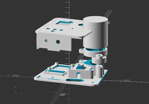
Assembling the INTVAL 2.0 can be done in an hour or so, much quicker if practiced. As mentioned, the largest amount of time should be in fabricating the parts or acquiring electronics/parts. There are 2 things I don't like about this design that I'll be addressing in subsequent builds: complexity of the electronics and crowding inside the case.
Mounting the electronics
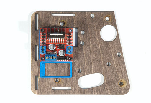
The L298N is attached to the panel via the three M2 bolts. The space cut in the panel where the fourth would go is to prevent the Bolex's handle from rubbing against the panel. At this point I usually flash the Arduino Trinket Pro with the latest firmware, as in the "Programming" section, prior to soldering and mounting. It can be done after, though, and can be reprogrammed after it is built.
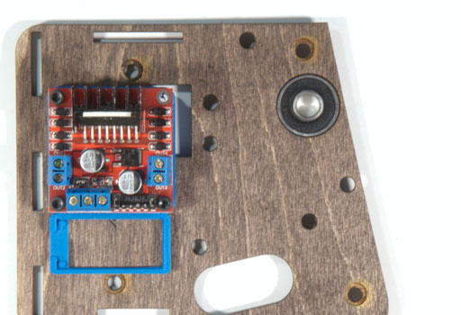
Attaching the bearing
Mounting the motor's base and microswitch
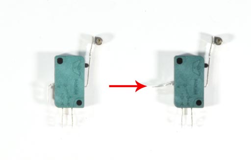
Modify the microswitch as shown in the photos. Be careful not to break the tab by over-exerting it at the bend. At this point, I usually solder leads onto the two tabs as shown below to save a cramped soldering job later. Insert the microswitch into the motor_mount_bottom and line the piece up with the 6 holes cut in the panel according to the pictures and rendering. It then gets attached to the panel with 4 of the M5 bolts and attached on the bottom with the corresponding M5 nuts.
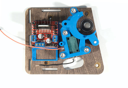
Mounting the motor
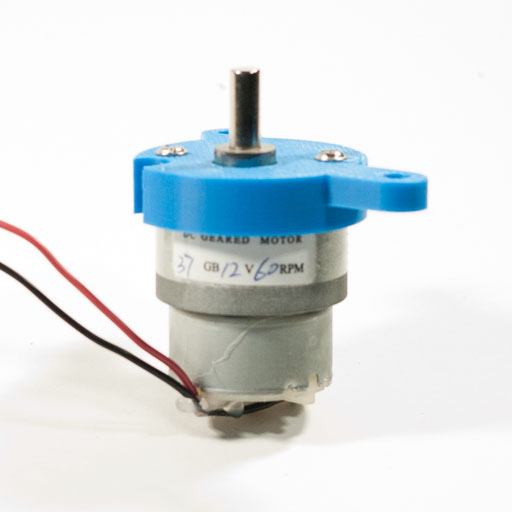
The motor should fit snugly into the motor_mount piece and can be attached with 2 screws that usually accompany the motor (when bought from Amazon). At this point, I usually solder 2 leads onto the top of the motor and cap it so that the fragile tabs wont break off. I use red and black wires so that I can easily switch their position in the L298N if the intervalometer is functioning backwards.
Attach buttons
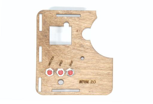
Three of the buttons are attached to the corresponding holes in the panel. The size of these holes might have to be modified depending on the type of momentary buttons you settle on. When cutting the panel cover, I will also add an etched-in label for each specifying (left to right) that they control direction, speed, and delay.
Attaching the DC and 3.5mm sockets
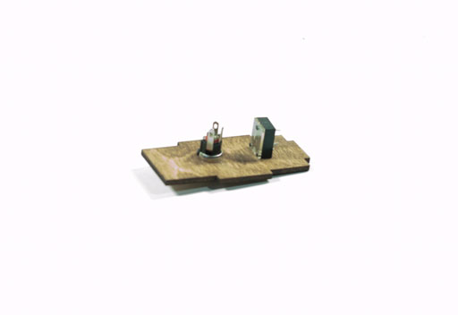
Attach the 2.1mm DC socket and the 3.5mm audio socket to the bottom panel of the board, using the bolts to secure them.
E. Soldering
Use of the $10 Arduino Trinket Pro 5V is explicitly due to the number of buttons required for the user interface. If you wanted to drop one of the buttons, say the speed control, you could re-write the sketch to use a $7 Arduino Trinket 5V (or get them in bulk for more savings). I mention this because it was the target microcontroller breakout for the project but had to be upgraded to the pro model to support all of the features in the design.
Digital pin utilization is as follows:
- PIN 3 - Shutter release
- PIN 4 - Delay button
- PIN 5 - Speed button
- PIN 6 - Direction button
- PIN 9 - Motor forward (L298N)
- PIN 10 - Motor backward (L298N)
- PIN 13 - LED indicator (built in to Trinket Pro)
- PIN 19 - Microswitch (aka A5)
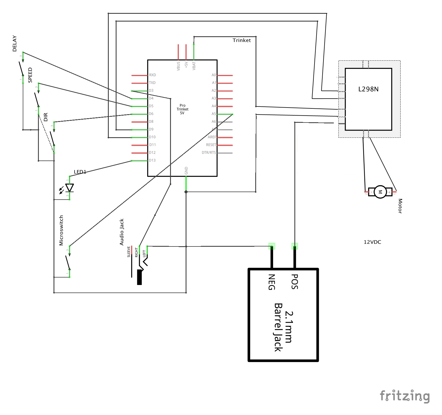
The Fritzing project requires the following libraries:
E. Building the shutter release (plunger)
To trigger the intervalometer and to start/stop sequences, the INTVAL 2.0 uses a simple switch that I found is handily made from cheap audio parts. In a pinch, this switch can be hard-wired into the design, but for the safety of the electronics inside I decided on using a 3.5mm socket and 3.5mm cable with a simple momentary button closing the circuit. For this, I buy a 6' cable and cut it in two.
Pull the cable through the small bottom cap of the plunger body (important) and solder both of the leads to the two tabs of the button. The bottom cap might have to be modified to better accommodate the size of the 3.5mm audio cable you end up using. Insert the button into the plunger body and fasten with the nut provided with the button. Then attach the bottom cap to the body. At this point, I usually use hot glue to prevent too much force being applied to the solder points.
G. Programming
This step should be done carefully, and with some practice. For a good primer on the basics of programming the microcontroller, check out Adafruit's tutorial on it. Arduino Trinket Pros enter into a short firmware-writable state when first plugged into a USB source. This is marked by the pulsing of the red indicator LED on the board.
If using the Arduino IDE, make sure you have the latest version and have read through this primer before you try to upload the sketch to the Trinket Pro. While the red LED is flashing, upload the sketch provided in this repository and that's it. Any modifications to the code can be made and flashed onto the board as many times as you'd like. Please feel free to submit pull requests if you make any improvements!